Math Monday: Linkages – An introduction
by Glen Whitney
[sharethis]
 There is perhaps no topic that has brought the worlds of math and practical construction so close together as the study of linkages. These are mechanical systems of bars and joints (and sometimes plates and hinges and slides, but we’re going to stick with bars and joints for a while…) which are free to move in a plane (or in space, but again, two dimensions will keep us plenty busy) and whose motion accomplishes some purpose or creates some pattern or curve. We constantly benefit from linkages. They appear in engines, in your car’s suspension, the mechanism of a steam shovel, and in your knee, just to mention a few places.
Today, we’re proud to present the MoMath Linkage Kit so that you, too, can explore the wonderful world of mathematical linkages. You can download the PDF file of the pieces in the kit via this link. You then have a variety of ways to actually fabricate the pieces. You can print the diagram out on the largest, heaviest cardstock you can manage to print on, and then use brass paper fasteners to make the joints, or if your print is too small, staple the pieces so that one leg of the staple goes through the center of the holes and the other side of the staple is off the paper. Note that you then may have to break off the other leg of the staple to get full rotation of your linkage. Also, if you are making paper copies of the linkages, note that all of the small sticks and the washers to the right of the page can be safely ignored.
Or, if you have access to a laser cutter or other automatic cutting device (anyone want to water-jet these out of bronze for us?), you can cut these pieces from a layer of other material. Note the kit is sized for an 18″ x 32″ sheet, 0.23″ thick (that was the actual thickness of the nominal quarter-inch acrylic we were using here at MoMath Labs). If you cut out the pieces in a material (like acrylic) that has a bit of give, when you line up the holes in two of the bars, you can insert one of the small sticks from the top right of the diagram and it will push through the holes and thanks to the slight flares, lock in place and produce a smoothly rotating joint. There are also locking sticks for three- and four-layer joints, and spacers that you may need to keep each bar in a plane, when you are building some of the more complex linkages with a thick material. If you are using a sheet of a different thickness, you may need to adjust the length of the locking sticks, and quite possibly their width and the size of all of the pivot holes (since the thickness of the material becomes one of the cross-sectional dimensions of the locking sticks).
Oh… and instructions for making the linkages? You’ll find those right here in Math Mondays, as we give you a tour of (a small part of) what can be accomplished with linkages over the next few weeks. Ready to start building? Let’s begin with a very familiar linkage that you’re quite likely to have used at some point.
But first, some general instructions: Each bar is labeled with its length, from center to center of the holes near the ends, in consistent units relative to all the other bars (1 unit = 3/8 inch if you print the Kit to full scale, incidentally). Some bars have additional holes. When there is a need to refer to one of these additional holes, it will be labeled by the distance in units from one end of the bar. For example, it should not be hard to find in the Kit the 60-bar with four holes, a 0-hole, 30-hole, 45-hole, and 60-hole. When a bar has been identified with a letter, like C, the directions will just refer to its 45-hole (say) as C45. Sometimes the directions will instruct you to make a link with a pen. If you fabricate at full size, a commonplace felt-tip pen squeezes snugly into the linking holes. At other scales, you will have to experiment — maybe a gel pen, or the tip of a Sharpie, or a thick lead from a compass or other drawing tool, etc. Anyhow, anything that will make the mechanical linkage and leave a mark as it moves will do.
Here’s your first recipe:
Scissors Jack
Ingredients: Four 60-bars with 30-holes (A, B, C, and D); two 30-bars (E and F); six linking sticks; two pens
Directions: Link A30 and B30. Link A60 to C0, B60 to D0, and C30 to D30. Link C60 to E and D60 to F. Link the free ends of E and F with a pen.
When that’s done, you should have a linkage that looks like this: You will note that you can move that pen quite a ways out by bringing the two free ends of the the bottom 60-bars together. That’s the mode in which this linkage is used, for example, as the mount of an extending mirror. But we are going to see what this linkage does as a drawing tool. So fix one of the free ends so it can pivot. (Slide it onto a fixed vertical rod, tape a spacer down and use a linking stick, or just have a friend hold it in place…) and put a pen in the hole at the other free end. Now as you draw with that pen (as seen in the opening image).
The other pen moves and draws in response: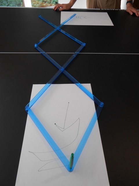 And here are the original and resultant drawings side by side in their proper orientations, so you can see the relationship. Note the magnification, and the change in direction: the scissors jack moves perpendicular to the direction of input motion, a fact you can appreciate if you’ve ever changed a tire on the roadside.
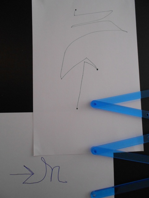 (Also note the replica is not quite perfect, of course, as there is a bit of “slop” in the links constructed in this way.)
Next time, we’ll start to build a repertoire of linkages, from the simplest on up.
This article first appeared on Make: Online, July 30, 2012.
